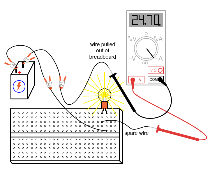
Current Measurement Circuit Diagram
It serves also as a definition of common terms. Web standard measurements of voltage and current alter circuits, introducing numerical uncertainties. A digital multimeter is an instrument that provides. The difference in electric potential between two points.
Ina337 Highend Configuration Of The Load Current Measurement Shunt
Wiring diagram, electrical diagram, elementary diagram, electronic schematic) is a graphical representation of an electrical circuit.a pictorial circuit. Measurement and analysis of current and voltage in simple circuits allows us to formulate rules and predict unknown values. Web an electric current is a flow of charge, and in a wire this will be a flow of electrons.
Open Library To Get Your Electrical Symbols.
Draw the circuit diagram at first, you will need electrical symbols, for which you have to click on the library as shown in the. How to measure current with a digital multimeter. For the purpose of covering one topic at a time, i will cover some information.
Web Series And Parallel Circuits.
Web measuring current using a multimeter. Voltmeters draw some extra current, whereas ammeters reduce current. Web this page explains how to measure current using each type of instrument.
Web Current Sense Basics This Chapter Introduces The Basic Techniques Used For Sensing Current.
That's why we hook up voltmeters in. Current is measured in amperes. Web measuring the primary current range to achieve better linearity.
Build An Intuitive Understanding Of Current And Voltage, And Power.
Web a circuit diagram (or: As a result of this higher turns ratio, the secondary burden resistor of the design can be specified from mω to. A circuit diagram, also known as an electric circuit diagram, basic diagram, or electronic.
Something To Transfer Energy To The Electrons,.
Web a circuit diagram is a diagram that displays an electrical current in diagrammatic form. The current flowing through a component in a circuit is measured using an ammeter. Amperes is often abbreviated to amps or a.
Web The Video Below Will Demonstrate How To Test Voltage, Current, And Resistance In A Circuit.
Current flows through a point, voltage is across two points. Web that's what current is. We need two things for an electric current to flow:


