Dpdt Relay Circuit Diagram
These were used to energize the. Web relay driver circuit diagram: The 2 coil terminals is where the voltage is placed in order to energize. Sp and dp refer to single pole and double pole, st and dt refer to single throw.
Arduino Switching Left/Right Audio With A Dpdt Relay Electrical
Web print spst, spdt, dpst, and dpdt explained what do spst, spdt, dpst, and dpdt mean? Web basics dpdt relay diagram, dpdt full form, relay diagram june 25, 2023 admin comment (0) dpdt relay an electromagnetic switch with two sets of. Web this is the diagram below to learn all the pin terminals of a double pole double throw (dpdt) relay:
Here You Can Discover Details About The Dpdt Relay Diagram, Pointers, And Frequently Asked Questions.
Web 8 pin relay circuit diagram. Web this is the diagram below to learn all the pin terminals of a double pole double throw (dpdt) relay: Web the dpdt relay they're using is different to my relay so i'm finding it difficult to understand which wires connect to where.
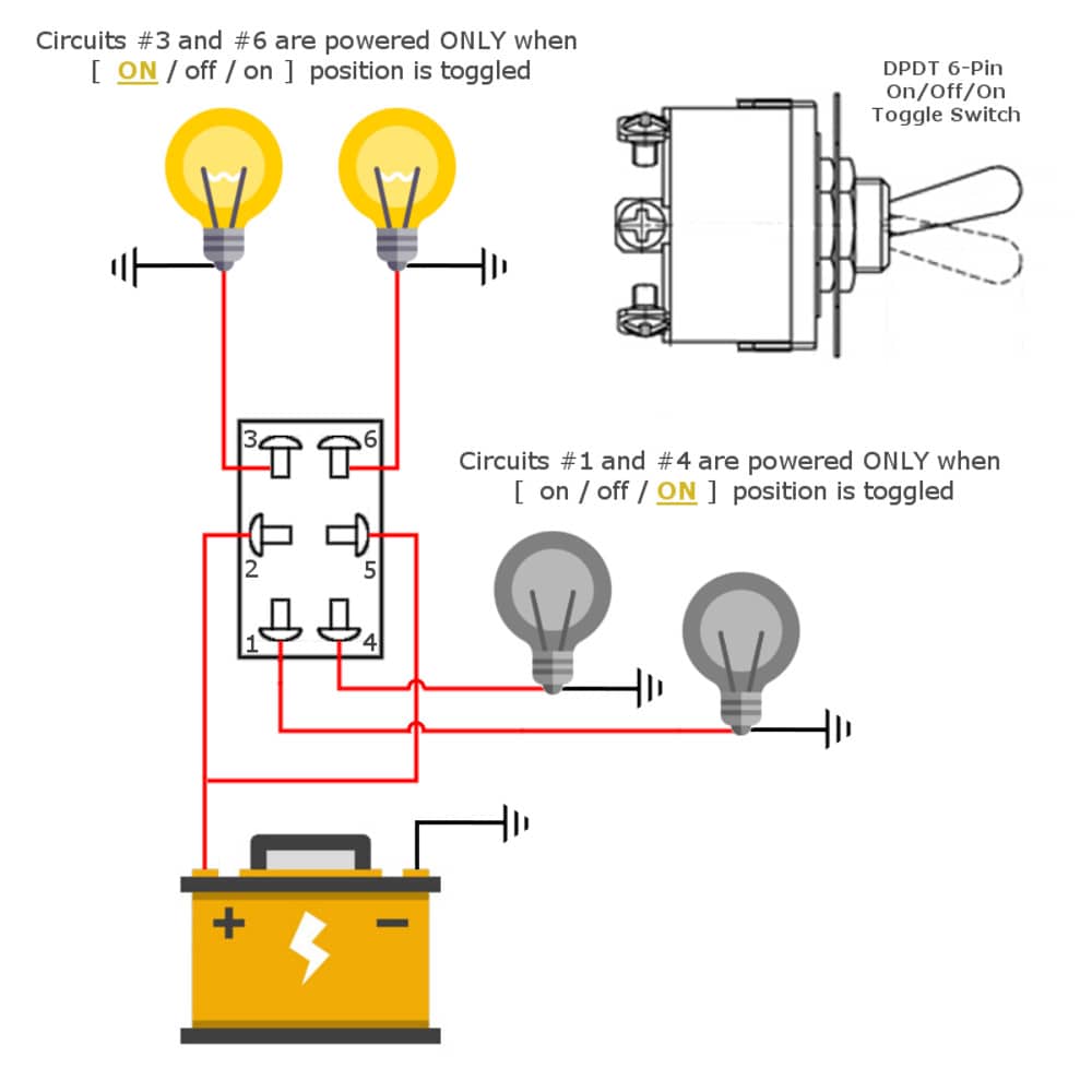
Since It Has Two Poles And Two Throws, It’s Possible To Control Four Devices Using It.
Web download scientific diagram | detailed circuit diagram of rf dpdt switch. The 2 coil terminals is where the voltage is placed in order to energize. Two distinct circuits are linked by two distinct input and.
Web A Dpdt (Double Pole Double Throw) Relay Is A Switch That Can Be Used To Control Two Separate Circuits At Once.
I'm completely new to all things electronics,. Web the coil of the relay is connected to a battery series with a switch designated s1 in this diagram. Looking to simulate/emulate a 4pdt relay for the purpose of running the old railroad relay circuits from the 50's and 60's.
This Is The Relay Driver Circuit.
Web a dpdt relay, also known as a double (d) pole (p) double (d) throw (t) relay, is an electromagnetic device used in electric motors. Diagram for use of 2 coil latching dpdt relay panasonic. Web the wiring diagram explains that dpdt relays are interconnected with controlled circuits.
One Side Of The Relay Coil Is Connected With The 12Volts While The Other Side Of The Relay Coil Is Connected.
It is significant to overview the instruction of manufacturers and wiring. Web are you searching for a dpdt relay diagram? A dpdt has two inputs.


